Trend of high frequency circuit board for full scale 5G
Focusing on electronic component/material manufacturers, each company is focusing on the development of materials/technologies for ultra-low transmission loss of high-frequency circuit boards/printed wiring boards.
Behind that is 5G (fifth generation mobile communication system), which has started commercial services all over the world.
The frequency band of radio waves used as a carrier of a transmission signal in 5G is divided into two major bands, a sub-6 band that is 6 GHz or less and a millimeter band that exceeds 24 GHz (including the quasi-millimeter wave band). Separately, at the moment, the introduction of 5G is progressing mainly in the use of Sub-6 band, and it is said that full-scale use of millimeter waves is a little further ahead.
However, one of the major features of 5G is the use of this millimeter wave. By using this millimeter wave band, it is thought that the world of ultra-high speed, ultra-multi terminal connection, and ultra-low latency communication will be realized in 5G.
However, the optimum solution of how to handle millimeter-wave band radio waves in mobile communication systems has not yet been derived, and the search for it is still ongoing.
In the fields of circuit boards and printed wiring boards, we are developing materials and technologies that are optimal for communications in the millimeter wave band.
Therefore, the first issue is the transmission loss of high frequency signals.
In a transmission line composed of wiring on a circuit board, the high frequency component of the signal is greatly attenuated compared to the low frequency component, and this characteristic is called transmission loss. In other words, high-frequency signals are more likely to deteriorate on the circuit board/printed wiring board than low-frequency signals, and the higher the signal frequency, the more noticeable it becomes.
There are several factors that contribute to transmission loss, but the factor called dielectric loss becomes dominant in the high-frequency signal region.
Dielectric loss is the loss of energy generated in a dielectric when an AC electric field is applied to the dielectric. The propagation of high frequency signals creates an alternating magnetic field, which causes dielectric losses in the substrate material.
How much the transmission loss is caused by this dielectric loss depends on the material of the substrate that is the transmission line. The parameter used to express the degree of this dielectric loss is called the dielectric loss tangent. A low value for this dissipation factor indicates low transmission loss.
It is also important to keep the signal delay low in a circuit board for high frequencies. The relative permittivity affects this signal delay amount. If the relative permittivity of the material of the circuit board is also small, it means that the signal delay can be kept small.
In other words, the dielectric loss tangent and the relative permittivity are two of the important parameters when studying the materials for high frequency circuit boards.
The figure below compares various materials with these two parameters as axes.
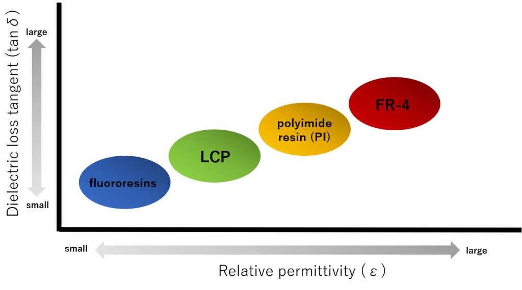
Of particular interest in these substrate materials are fluororesins (PTFE) and LCP (liquid crystal polymer). Compared with glass epoxy resin (FR-4) and polyimide resin (PI), which are often used as conventional board materials, the dielectric loss tangent and relative permittivity are smaller than other materials, and it is used as a circuit board material for high frequencies. Because it is suitable.
In addition, in order to suppress transmission loss, it is necessary to consider water absorption and conductor adhesion.
The dielectric loss tangent value of the material increases with the amount of water absorption, so a material with low water absorption is desired.
Conductor adhesion is the adhesion between the board material and the copper foil that will be the conductor. If this adhesion is low, it is necessary to roughen the copper foil surface to improve the adhesion. However, the roughening causes unevenness on the surface of the copper foil, increasing the electrical resistance and increasing the signal transmission loss, which is a demerit.
Murata Manufacturing is currently attracting attention in the circuit board business using LCP. Murata manufactures a resin multi-layer substrate, Metroserk, which has been available for iPhones from Apple in the United States from around 2016 to 2017, and from 2019 it is being supplied to other than Apple.
Kuraray, a long-established LCP company, is also steadily commercializing the world’s first liquid crystal polymer (LCP) film, realized with its unique film forming technology.At Saijo Works, we will increase production capacity for liquid crystal polymer film, Vexter, and at Kashima Works, we will introduce mass-production test equipment for copper-clad laminate <Vexter® FCCL> using the film and start shipping samples. doing.
AGC is focusing on fluoropolymers.
AGC is entering the copper-clad laminate (CCL) business, which utilizes its strengths in fluororesin.Specifically, we are increasing the production capacity of our own brand fluororesin Fluon+EA-2000 and acquiring the copper clad laminate (CCL) business from Perk, Inc. of the United States. It seems that they are focusing especially on rigid CCL.
I would like to pay close attention to future developments in this field.